Views: 0 Author: Cécile Favre, John May & Dirk Bosteels Publish Time: 2025-07-22 Origin: International Paper


In the most common type – wall-flow filters – particulate matter is removed from the exhaust by physical filtration using a honeycomb structure similar to an emissions catalyst substrate but with the channels blocked at alternate ends. The exhaust gas is thus forced to flow through the walls between the channels and the particulate matter is deposited as a soot cake on the walls. Such filters are made of ceramic (cordierite, silicon carbide or aluminium titanate (20)) honeycomb materials.
![]()

Figure 3: Exhaust gas flow through a wall-flow filter channel.
Ceramic wall-flow filters remove almost completely the carbonaceous and metallic particulates, including fine particulates of less than 100 nanometers (nm) diameter with an efficiency of >95% in mass and >99% in number of particles over a wide range of engine operating conditions (21). The latest European emissions limit values (i.e. Euro 5, 6 and VI) are set on the basis of both mass and number counts to ensure control of the ultrafine particles, which are thought to be more critical indicators of health impact.
Since the continuous flow of soot into the filter would eventually block it, it is necessary to 'regenerate' the filtration properties of the filter by burning-off the collected particulate on a regular basis. The most successful methods to achieve regeneration include:
- Incorporating an oxidation catalyst upstream of the filter that, as well as operating as a conventional oxidation catalyst, also increases the ratio of NO2 to NO in the exhaust (22). NO2 provides a more effective oxidant than oxygen and so provides optimum passive regeneration efficiency.
- Incorporating a catalytic coating on the filter to lower the temperature at which particulate burns. New formulations and process development intend to lower backpressure (23) and to substitute platinum by palladium where ultra-low sulfur fuels are available. In (24), Pt/Pd formulations at a 3:1 ratio had lower light-off temperature (the temperature at which the catalyst starts to work) than Pt-only catalysts (240°C vs. 295°C) in the aged state, generated as much NO2 for passive soot oxidation, and were resistant to sulfur contamination. In one investigation (25), platinum was completely substituted for palladium with use of a base metal catalyst. New formulations are using ceria or zirconia to make the soot react directly with oxygen at the catalyst-soot interface. One paper (26) shows a new zirconia-based soot catalyst that transfers oxygen from the gas to the soot-catalyst interface for 70% faster soot oxidation rates at 75°C lower temperatures. Enhanced versions based on ceria are showing potential to oxidize soot at temperatures as low as 260°C with very little precious metal (27).
- Using very small quantities of Fuel-Borne Catalyst (FBC), such as ceria (28) or iron additive compounds added to the fuel using an on-board dosing system. The FBC, when collected on the filter as an intimate mixture with the particulate, allows the particulate to burn at lower exhaust temperatures (around 350°C instead of 650°C) and increases the combustion kinetics (typically 2-3 minutes) while the solid residues of the catalyst are retained on the filter as ashes. The third generation of FBC (29) is based on 3 ppm iron allowing a 1.7 litre tank to last the life of the vehicle (240 000 km) and requiring no process for ash cleaning.
![]()

Figure 4: Fuel-borne catalyst dosing unit.
- Fuel injector placed in the exhaust line upstream of the DPF (30). This provides a source of hydrocarbons to initiate the temperature rise for regeneration.
- Electrical heating of the trap either on or off the vehicle (31) and (32).
Trapped particulate burns off at normal exhaust temperatures using the powerful oxidative properties of NO2 and can burn in oxygen when the temperature of the exhaust gas is periodically increased through post-combustion. Maximum exothermic temperatures must be controlled, especially in worst-case ‘drop-to-idle’ conditions when the soot combustion starts at high temperature and flow and then the engine drops to idle (33).
One study suggests that a Diesel Oxidation Catalyst is needed to get higher temperatures at the inlet face of DPF to assist the first centimeters to regenerate (34).
As the understanding of DPF fundamentals has moved forward, a porous membrane can now be added to the inlet wall so that soot is kept out of the wall (35). This improves filtration efficiency and back-pressure, as well as the correlation between back-pressure and soot loading. This correlation can be used for OBD purpose and for example, soot models using wall permeability algorithms have been developed (36). Soot sensors may also be needed in the future. Sensor concepts are being tested and compared (37). Concepts include using charge transfer by soot from one charged plate to another and using PM film electrical property measurement.
![]()
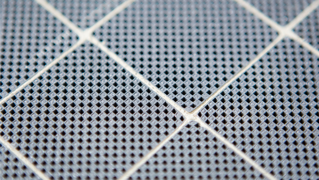
Figure 5: wall-flow particulate filters.
Diesel Partial-Flow Filters normally use a metallic substrate. The metallic partial-flow filter uses a special perforated metal foil substrate with a metal 'fleece' layer so that the exhaust gas flow is diverted into adjacent channels and the particles are temporarily retained in the fleece before being burnt by a continuous reaction with the NO2 generated by an oxidation catalyst located upstream in the exhaust. It offers an option for reducing PM emissions by 30-60% (38).
![]()

Figure 6: Diesel partial-flow filters.
So-called open filters are available in various materials from fibre-based to metallic ‘foams’. ‘Open’ filters do not have a storage function. Their efficiency is normally limited and they are usually used in some retrofit applications (39).